In modern manufacturing, the primary bottleneck has decisively shifted from basic assembly to rigorous quality control. Choosing between dedicated inspection solutions and flexible standalone setups is no longer merely a technical preference. You are making a critical decision. This choice directly defines your production margins and factory efficiency.
General-purpose machines provide excellent flexibility for varied manufacturing runs. Conversely, specialized inline systems guarantee unmatched throughput for high-volume tasks. However, hidden operational challenges often disrupt your expected returns. You might face frustrating programming delays. You could experience high false call rates. Complex integration hurdles also create unexpected downtime.
This comprehensive guide strips away common marketing claims. We objectively evaluate these two distinct inspection architectures. We provide an evidence-based framework tailored for production managers and procurement engineers. You will learn how to align machine capabilities with your specific factory floor realities. We will help you optimize your quality control strategy.
Application Fit: CG AOI equipment is purpose-built for high-volume, low-mix 3C inspection equipment lines (e.g., Cover Glass, displays), whereas single unit AOI excels in high-mix, medium-volume PCBA environments.
Cost Realities: Single unit AOI requires lower initial CapEx, but CG setups drive lower overall operational expenses at scale through reduced operator intervention and automated handling.
Performance Metrics: The true test of either system lies not in marketed megapixel counts, but in false-call reduction and programming speed during product changeovers.
You must understand the foundational differences between these architectures before making procurement decisions. Each system serves completely different production philosophies. They use distinct hardware frameworks. They solve different quality control problems.
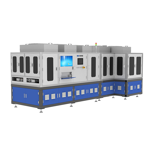
Specialized CG AOI equipment represents the pinnacle of automated surface inspection. Engineers design these automated optical inspection systems specifically for consumer electronics components. They excel at cover glass defect detection. They integrate directly into your moving production line.
Core Strength: These systems utilize optimized lighting arrays. They rely on advanced imaging algorithms.
Specialization: They tune specifically for surface anomalies. These include micro-scratches, subtle edge chips, and invisible micro-cracks. They do not focus on standard solder joint defects.
Automation: They feature seamless pass-through conveyors. This eliminates manual loading completely.
A traditional single unit AOI station functions as an independent module. Operators typically load these machines manually. You place them off-line away from the main conveyor system.
Core Strength: High versatility defines this category. You can easily redeploy these machines across different production lines.
Specialization: They handle a massive variety of standard printed circuit board (PCB) assemblies. They identify missing components and bad solder joints perfectly.
Footprint: They require minimal facility preparation. You simply plug them in and start programming.
Production managers face a constant balancing act. You demand metrology-grade precision in consumer electronics applications. However, you also want to avoid the financial risk of over-specializing your capital equipment. Standalone units feel safer for unpredictable future contracts. Specialized inline units deliver the massive throughput required for tier-one supply chains. Your specific product mix must dictate this choice.
Spec sheets often mislead buyers. High megapixel cameras do not guarantee better inspection results. You must evaluate machines based on actual production outcomes. We focus on defect resolution, system throughput, and optical capability.
Traditional rule-based thresholding powers basic standalone units. These systems use rigid geometric parameters. If a pixel block exceeds a certain contrast level, the machine flags a defect. This works adequately for clear-cut PCB solder issues. It fails miserably on complex glass surfaces.
Modern inline systems utilize AI-driven defect classification. They learn acceptable cosmetic variations. Dust particles do not trigger alarms. The system understands the difference between a critical micro-crack and a harmless tooling mark.
The Over-Reject Problem:
Evaluate how each system handles acceptable variances. Some manufacturers boast a 0% escape rate. However, they hide a 20% false-positive rate. This dynamic simply shifts your production bottleneck. The machine catches every real defect, but it also flags thousands of perfect parts. Manual reviewers must then sort through these false alarms. Operator fatigue sets in quickly. They eventually approve genuinely defective parts by mistake.
Handling mechanics dictate your true cycle time. Standalone units incur massive load and unload latency. An operator must pick up the part. They place it in the fixture. They press a button. The machine scans. The operator removes the part. This manual handling adds crucial seconds to every single cycle.
Dedicated inline setups feature continuous pass-through architecture. They cut cycle times drastically. They match your upstream assembly speeds perfectly. The board or glass panel glides into the machine. The system inspects it instantly. The conveyor moves it along without hesitation.
Cycle Time Comparison Chart | ||
Operational Phase | Standalone General Purpose System | Dedicated Inline System |
|---|---|---|
Loading Mechanism | Manual operator insertion | Automated SMEMA conveyor |
Positioning Delay | 3 to 5 seconds per unit | Sub-second automated alignment |
Inspection Speed | Standard camera traverse | High-speed synchronized strobing |
Unloading | Manual removal required | Continuous downstream feed |
Consumer electronics demand extreme optical precision. Sourcing the right 3C inspection equipment requires scrutinizing the light source. Glass, polished metals, and transparent plastics reflect light aggressively.
Specialized systems utilize multi-angle, multi-spectrum lighting. They employ coaxial lights to highlight internal cracks. They use low-angle dome lights to illuminate surface scratches. These machines cycle through different light spectrums instantly during a single capture.
Standard standalone units struggle with highly reflective surfaces. They often create intense glare. This glare blinds the camera sensor. The machine misses critical defects hidden beneath the bright spots. You cannot inspect polished smartphone displays effectively using standard white ring lights.
Hardware capabilities represent only half the equation. You must consider how these machines integrate into your existing factory ecosystem. Software friction and facility requirements can derail a successful deployment.
Standalone units often demand manual CAD or Gerber file matching. Technicians must tweak parameters per batch. They spend hours adjusting thresholds. This creates significant machine downtime during product changeovers. You lose valuable production hours every time you switch product lines.
Evaluate whether the dedicated software offers smart programming features. Look for offline programming capabilities. Your engineers should write the inspection recipe on a separate computer. They then push the program to the active machine. This minimizes downtime completely. Advanced AI models also automate the parameter-tuning process. They suggest the best lighting and threshold settings automatically.
Facility layout impacts your purchase decision heavily. Standalone stations save valuable floor space. You squeeze them into corners. You do not need to break your existing conveyor lines. You simply wheel them where you need them.
Dedicated equipment demands rigorous inline integration. You must plan the layout carefully. These systems require precise vibration control. Heavy forklift traffic nearby can blur metrology-grade images. Furthermore, you must establish robust upstream and downstream handshake protocols. Your machines must communicate seamlessly using SMEMA or IPC-HERMES standards. The inspection unit must tell the upstream conveyor to halt if its internal buffer is full.
Assess the user interface carefully during vendor demonstrations. Complex 3D inspection tools require higher-level engineering oversight. They use intricate point-cloud data. They require deep knowledge of optics. You cannot hand these systems over to entry-level technicians immediately.
Conversely, standalone legacy systems offer technician-friendly interfaces. The software resembles a simple smartphone app. The learning curve remains shallow. You must weigh your current workforce capabilities against the machine's complexity. Do not buy a system your team cannot operate without constant vendor support.
You must map your specific operational scenarios to the right technology. Use the following framework to guide your final decision. Do not let vendor marketing push you into an unsuitable architecture.
You operate a high-mix, low-to-medium volume facility. Your factory handles New Product Introduction (NPI) lines or prototype shops. You change products multiple times a day.
You require frequent redeployment. You move inspection stations across different product types regularly. Flexibility trumps raw speed in your environment.
You inspect standard PCB assemblies. Your primary defects involve missing components, skewed chips, or bad solder fillets. You rarely inspect complex, transparent, or highly reflective surfaces.
Your floor space remains highly restricted. You cannot afford to break existing conveyor lines or dedicate large physical footprints to single processes.
You operate as a dedicated tier-1 supplier. Your clients demand massive volumes. You run continuous, low-mix production shifts.
Your materials are highly complex. You inspect reflective surfaces, transparent glass, or complex metallic housings. You need multi-angle, multi-spectrum lighting.
Quality compliance mandates zero-touch traceability. You require metrology-level data logging. The system must automatically upload defect coordinates to your Manufacturing Execution System (MES).
Manual loading creates unacceptable bottlenecks. Your upstream assembly pushes parts faster than human operators can handle them. You need seamless inline pass-through capabilities.
Do not request a formal quote yet. You must conduct a Gauge R&R (Repeatability and Reproducibility) test first. Bring your actual production samples to the vendor's demo facility. Include parts with borderline, highly ambiguous defects. Run them through the automated optical inspection systems multiple times. Demand the vendor prove their false-call reduction claims using your specific materials. This real-world test eliminates theoretical marketing promises instantly.
The choice between dedicated inline solutions and standalone units carries immense weight. You cannot make this decision based on glossy spec sheets alone. It hinges entirely on your specific production volumes. It depends on your unique defect profiles and workforce availability.
Analyze your true bottlenecks. Focus on false-call rates rather than raw machine speed. Over-rejects kill production efficiency faster than slow conveyors.
Avoid over-speccing. Buy machines to solve the specific defects currently costing you money. Do not purchase expensive features for theoretical edge cases you may never encounter.
Prioritize software over hardware. An average camera paired with brilliant AI and seamless offline programming outperforms high-end optics running clunky, rigid software.
Evaluate integration readiness. Ensure your factory floor can support the vibration control and data networking required for metrology-grade inline systems.
Take proactive steps today. Engage with trusted vendors for a rigorous proof-of-concept (POC). Use a known batch of flawed components. Measure the true false-call rates in a simulated, real-world scenario before signing any purchase orders.
A: Partially. You can sometimes retrofit software and newer cameras. However, the physical handling mechanisms often fall short. Specialized multi-angle lighting requires substantial space. It usually exceeds the mechanical limits of standard standalone frames. You cannot easily mimic true metrology-level environments in modular setups.
A: AI significantly reduces false positives. It learns acceptable cosmetic variations, such as harmless dust or minor tooling marks. It does not rely on rigid geometric thresholds. This adaptability gives you a critical advantage when inspecting complex consumer electronics surfaces.
A: Standalone units generally require standard calibration and basic optical cleaning. They are relatively simple to maintain. Dedicated inline systems require rigorous attention. You must perform regular alignment checks on conveyor mechanisms. You must tightly calibrate specialized lighting arrays and execute frequent software tuning.