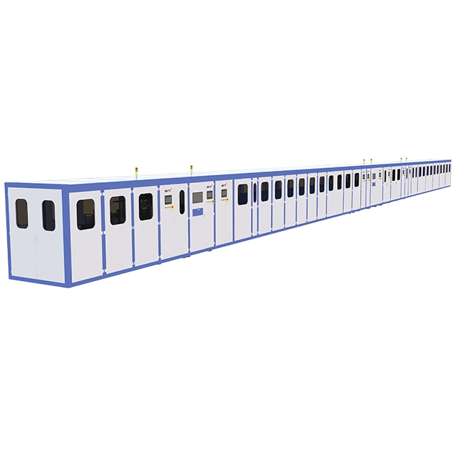
Thermistors and other temperature-sensing components are small, but their surface quality has a direct effect on downstream assembly, electrical performance, and product reliability. After soldering and coating, defects can be difficult to identify consistently through manual observation alone. A practical solution is to place dedicated automated vision inspection equipment at the required inspection stations of the customer’s existing production line.
In this application, the Matsuba Component AOI inspection equipment is used for thermistor surface defect inspection rather than as a complete assembly production line supplied by PTC. The inspection solution can be connected to the customer’s line to check soldering appearance, critical dimensions, coating appearance, and coating dimensions. This article explains the main benefits of that approach and the inspection tasks it can support.
Key Takeaways
Focused inspection scope: The solution is designed around automatic surface defect and dimension inspection after thermistor soldering and coating.
Production-line compatibility: The AOI equipment can be integrated with the customer’s existing material flow and control system instead of replacing the customer’s assembly line.
Consistent defect judgment: Machine vision reduces the variation that can occur when different operators judge small solder and coating defects.
Traceable quality data: Inspection results, batch information, yield data, and defect images can support quality analysis and process improvement.
What the Equipment Is Designed to Do
The equipment is best understood as a thermistor surface defect inspection solution that works with a customer’s production process. It does not need to perform component assembly in order to create value. Its main role is to inspect parts automatically at critical quality-control points, identify visible defects, verify dimensions, and send inspection results to the production or quality-management system.
Within PTC’s intelligent inspection equipment range, the Matsuba component solution focuses on two essential stages: soldering surface defect inspection and coating surface defect inspection. These stages are important because a defect that escapes the soldering station may be hidden or made more difficult to evaluate after coating. Likewise, a coating problem can affect protection, dimensions, handling, or later installation.
The inspection equipment can be positioned after soldering, after coating and curing, or at both points, depending on the customer’s process. Line-interface details such as loading direction, part presentation, trigger signals, reject handling, communication protocol, and data exchange should be confirmed during project evaluation.
Automatic Inspection After Thermistor Soldering
Soldering creates both electrical and mechanical connections, so appearance inspection must look for more than a simple “present or absent” condition. Small thermistor components may be attached to leads or carriers, and even a slight positional shift can affect the next coating, forming, or assembly step. An AOI system uses controlled lighting, industrial cameras, image-processing software, and product-specific inspection recipes to examine each component under repeatable conditions.
Soldering Defects That Can Be Checked
According to the referenced product application, inspection items can include lateral or vertical misalignment, chip rotation, solder wetting problems, solder balls, and solder bridging. The exact defect library should be confirmed with the customer’s samples, acceptance criteria, and process limits. During project setup, qualified and defective samples are used to establish the visual boundaries between an acceptable solder joint and a reject condition.
Misalignment: Detects a component that is shifted, tilted, or rotated beyond the permitted position.
Solder wetting defects: Identifies abnormal solder coverage or joint appearance that may indicate an unstable process.
Solder balls: Finds unwanted solder particles near the component or lead area.
Solder bridging: Detects unintended solder connections between adjacent conductive areas.
Dimensional deviation: Checks selected distances, positions, or component geometry against the approved inspection recipe.
Why AOI Is Useful for Small Soldered Components
Thermistor components are compact, and the difference between a qualified joint and a marginal one may be subtle. Manual inspection can be affected by operator fatigue, viewing angle, lighting changes, and different interpretations of the standard. Automated inspection applies the same decision logic to every inspected part. This supports stable quality judgment during long production runs and makes defect trends easier to compare across shifts and batches.
Coating Appearance and Dimension Inspection
After soldering inspection, many temperature-sensing components receive a protective coating. The coating must cover the intended area without creating unacceptable cracks, chips, protrusions, contamination, or dimensional variation. Because the coating changes the component’s external profile, both cosmetic inspection and dimensional verification are important.
The Matsuba component inspection application can evaluate coating length and critical diameter while also checking visible surface defects. Typical inspection items listed for the product include cracks, chipping, protrusions, contaminant adhesion, and insufficient coating. These checks help the customer prevent visibly defective or dimensionally unsuitable parts from moving to the next manufacturing stage.
Typical Coating Defects
Inspection Item
What the Vision System Evaluates
Why It Matters
Coating length
Whether the coated region stays within the defined upper and lower limits
Supports consistent coverage and downstream fit
Critical diameter
Whether the coated component profile exceeds or falls below the permitted dimension
Helps control installation and packaging compatibility
Crack or chipping
Broken, split, or missing coating areas
Prevents visibly damaged parts from continuing downstream
Protrusion or deformation
Abnormal material shape outside the approved contour
Reduces interference during later handling or assembly
Contaminant adhesion
Foreign particles or abnormal spots on the surface
Improves appearance consistency and process cleanliness control
Insufficient coating
Areas where expected coating coverage is incomplete
Supports stable protective coverage
Benefits of Thermistor AOI Equipment
1. More Consistent Quality Judgment
A defined inspection recipe applies the same image conditions, measurement rules, and defect thresholds to every part. This reduces dependence on subjective visual judgment and helps maintain consistent inspection criteria across different shifts.
2. Earlier Defect Containment
Placing AOI directly after soldering allows the customer to identify solder-related defects before coating or further processing. Early containment prevents additional work from being added to a part that is already defective. A second inspection after coating can then focus on surface quality and dimensional conformity.
3. Connection to Existing Production Lines
The customer does not need to treat the inspection station as a separate offline activity. The equipment can be engineered to receive parts from the customer’s existing line, inspect them, communicate pass/fail results, and support the customer’s chosen reject or transfer method. The exact mechanical and electrical interface is defined around the customer’s production conditions.
4. Defect Data and Traceability
Inspection software can display real-time results and support data query, export, and analysis. Production data, product batch information, yield statistics, defect categories, and selected images can provide a clearer record of what happened during production. When connected with the customer’s MES or quality system, these records can support traceability and root-cause analysis.
5. Flexible Recipes for Different Product Models
Thermistors may vary in body size, lead geometry, coating profile, or acceptable defect limits. Template and parameter configuration allows the inspection system to support multiple product models. Before a new model is released, its recipe should be validated using representative qualified samples and known defect samples.
6. Support for Process Improvement
AOI data does more than separate good and defective parts. Repeated increases in a certain defect type may point to soldering temperature, material presentation, coating control, fixture condition, or upstream alignment issues. Trend data helps process engineers focus their investigation on the most frequent or newly emerging problems.
Manual Inspection Versus Automated Vision Inspection
Factor
Manual Appearance Inspection
Automated Vision Inspection
Judgment consistency
Can vary by operator and shift
Uses repeatable recipes and thresholds
Small-defect visibility
Depends on magnification, lighting, and attention
Uses controlled imaging and targeted algorithms
Dimension measurement
Often requires separate gauges or sampling
Can combine appearance and selected dimension checks
Data collection
May rely on manual records
Can record inspection results and defect statistics automatically
Line integration
May create a separate inspection step
Can be connected to the customer’s production line
How the Inspection Equipment Connects to a Customer Line
A successful project begins with the inspection target, not with a generic machine configuration. PTC and the customer need to define where the part enters the inspection station, how it is positioned, how the camera sees each required surface, and what happens after a pass or fail result. The equipment may exchange ready, busy, complete, pass, fail, alarm, and reset signals with the customer’s line control.
For projects involving different temperature-sensor structures, the related sensor chip AOI solution provides another reference for chip soldering and coating appearance inspection. However, the final configuration should always be based on the actual thermistor model, takt time, inspection standard, and site interface.
Recommended Project Inputs
Qualified samples and representative defect samples
Drawings with dimensional tolerances and inspection positions
Written defect definitions with pass/fail boundaries
Current line speed, takt time, and part spacing
Part loading direction and positioning method
Required communication signals and data fields
Reject handling and re-inspection requirements
MES, barcode, batch, or traceability requirements
Validation Before Production Release
Inspection equipment should be validated with the customer’s actual products before final acceptance. The validation plan should include qualified parts, clear defects, borderline samples, repeated runs, model changeover tests, and line-interface checks. Measurement correlation may also be required for dimensional items.
False rejection and missed-detection risks must be evaluated together. Extremely strict thresholds may catch more questionable features but can also increase unnecessary rejects. Thresholds that are too loose may allow meaningful defects to pass. A balanced recipe is established through sample testing, defect review, and agreement on the customer’s quality standard.
FAQ
Is this equipment a complete thermistor assembly production line?
No. PTC provides surface defect inspection equipment that is designed to connect with the customer’s existing production line. The primary scope is automated inspection after soldering and after coating.
What defects can be inspected after thermistor soldering?
Depending on the validated inspection standard, items may include component misalignment, chip rotation, solder wetting problems, solder balls, solder bridging, and selected dimensional deviations.
What can be checked after coating?
The system can inspect coating surface defect and dimensions, including coating length, critical diameter, cracks, chipping, protrusions, contamination, and insufficient coating.
Can the equipment support more than one thermistor model?
Yes. Different models can be supported through separate inspection templates and parameter recipes, subject to sample validation and any required fixture or optical adjustments.
Can inspection data be exported?
The referenced equipment supports data query, export, and analysis functions. The final data format and MES connection should be confirmed during technical communication.
What information is needed before proposing an inspection solution?
Useful inputs include product samples, defect criteria, takt time, line layout, loading method, communication requirements, and expected data-traceability functions.
Conclusion
The main value of Matsuba component automated equipment in this application is not the supply of an assembly line. It is the reliable automation of thermistor surface defect inspection at the points where soldering and coating quality must be controlled. By combining repeatable imaging, defect recognition, dimensional checks, recipe management, and production data, the inspection equipment can help customers improve consistency and strengthen traceability while continuing to use their existing production line.
 English
 العربية
 Français
 Русский
 Español
 Português
 Deutsch
 italiano
 日本語
日本語 한국어
한국어 Nederlands
 Tiếng Việt
 ไทย
ไทย Polski
 Türkçe
 Bahasa Melayu
 தமிழ்
தமிழ் Filipino
 Bahasa Indonesia
 magyar
 Română
 Čeština
 Српски
 हिन्दी
 فارسی
فارسی Slovenčina
 Slovenščina
 українська
 Suomi
Suomi Հայերեն
 עברית
עברית Latine
 Shqip
Shqip বাংলা
বাংলা Eesti keel
 Oʻzbekcha
 latviešu
 Беларуская мова
 Esperanto