Please Choose Your Language


Manufacturers constantly battle quality control bottlenecks on their production lines. Subjective manual checks slow down output significantly. Relying purely on human eyes leads to missed flaws. It also creates costly false rejects. Standard optical systems attempt to solve this problem. However, they struggle to illuminate microscopic flaws accurately. Reflective glare and complex metal geometries confuse basic cameras. They often misinterpret harmless shadows as critical cracks. You need a better way to ensure reliable cosmetic grading.
Integrating magnetic principles solves this exact visibility problem. It forces quantifiable contrast around hidden surface flaws. This approach shifts quality control from a subjective bottleneck to a predictable process. It makes data-driven manufacturing a reality. In this article, you will learn how magnetic flux reveals invisible surface anomalies. We will explore how to integrate these systems seamlessly. You will also discover practical steps for evaluating hardware options for your specific production needs.
Enhanced Contrast for Micro-Flaws: Magnet cosmetic inspection equipment forces visible contrast at defect sites, revealing hairline cracks and surface anomalies invisible to standard optics.
Reduced False Rejects: Combining magnetic flux data with automated inspection algorithms standardizes cosmetic evaluation, minimizing subjective human error.
Integration over Replacement: Modern systems are designed to integrate with existing visual inspection equipment and production lines, rather than requiring total workflow overhauls.
Evaluation Focus: Successful adoption requires assessing throughput capacity, part geometry handling, and demagnetization requirements alongside baseline detection sensitivity.
Conventional optical cameras face severe limitations in industrial settings. They rely entirely on external lighting to capture anomalies. Highly reflective metal surfaces create severe optical challenges. A simple curved edge reflects light unpredictably. Textured metals create shadows across the entire component. This visual "noise" heavily confuses standard optical sensors. Basic cameras cannot differentiate between a structural crack and a harmless shadow. They simply lack the baseline contrast required for high-precision grading.
Human subjectivity further complicates cosmetic evaluation. Manual inspection introduces immense variability into the production line. Eye fatigue sets in after just hours on the floor. Operators lose focus easily during long shifts. Different technicians apply different baseline standards. A slight scratch might pass morning inspection but fail during the night shift. Inconsistent training compounds this variability. You simply cannot scale a subjective quality control process.
The financial cost of this inaccuracy grows quickly. Manufacturers face two distinct risks. First, they risk shipping defective parts to customers. This damages brand reputation instantly. It also triggers expensive product returns. Second, overly aggressive inspectors scrap perfectly functional parts. They flag harmless tooling marks as severe defects. This false-positive flagging destroys yield rates. You lose money on every scrapped component. Reliable surface defect detection must eliminate both risks simultaneously.
Magnetic flux leakage (MFL) provides the core physics for this technology. The equipment magnetizes the ferromagnetic component temporarily. Magnetic lines travel smoothly through solid metal. A crack or surface void interrupts these lines abruptly. The magnetic field cannot cross the empty air gap easily. Instead, it bows outward from the surface. This creates a localized flux leakage field. Specialized magnetic particles are then applied to the part. The leakage field pulls these particles directly into the flaw. They accumulate tightly at the defect site. This forces stark visual contrast exactly where the anomaly exists.
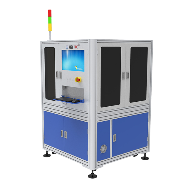
High-resolution machine vision systems then capture this artificially induced contrast. This creates powerful synergy. The magnetic field guarantees the flaw is visible. The camera simply records the data. Magnet cosmetic inspection equipment leverages this synergy beautifully. The specialized particles glow brightly under ultraviolet light. The camera captures brilliant indications against a dark background. This eliminates the reflective glare problem entirely. The vision system no longer guesses. It sees mathematical certainty.
This hybrid approach excels at categorizing distinct flaws. Software algorithms analyze the accumulated particle shapes. They distinguish between critical structural cracks and minor cosmetic irregularities. A deep crack draws massive amounts of particles. A shallow scratch draws very few. You can tune the equipment to threshold specific tolerances. The system ignores acceptable plating flaws. It flags dangerous inclusions instantly. You control the exact boundary between pass and fail.
Defect Type | Magnetic Flux Response | Optical Signature | Grading Action |
|---|---|---|---|
Structural Crack | High flux leakage | Sharp, dense particle line | Critical Reject |
Surface Scratch | Low flux leakage | Faint, dispersed particles | Tolerance Check |
Subsurface Inclusion | Medium, broad leakage | Fuzzy, clustered indication | Threshold Dependent |
Tooling Mark | No flux leakage | No particle buildup | Pass |
Buyers must evaluate hardware across several practical dimensions. Speed and compatibility remain top priorities. Visual inspection equipment upgrades must match your baseline production pace. A slow system creates a massive factory bottleneck.
You must assess how the equipment aligns with your line speeds. Magnetizing a part takes milliseconds. Applying the particle fluid adds seconds. Analyzing the image requires robust processing power. Does this cycle time slow down upstream assembly? The best systems utilize parallel processing. They magnetize one part while imaging another. Ensure the vendor guarantees specific cycle times for your exact component volumes.
Modern factories rarely produce single SKUs. Your system must handle complex geometries easily. It should inspect gears, shafts, and flat plates without extensive re-tooling. Evaluate its handling of varying ferromagnetic compositions. Different steel alloys require different magnetic field strengths. The equipment must offer programmable magnetization profiles. This allows rapid changeovers between product runs. Flexibility prevents costly hardware downtime.
Hardware provides the image. Software provides the decision. Look for systems utilizing machine learning. Deep learning models differentiate between true cosmetic defects and acceptable variations. They learn from historical image data. AI distinguishes a critical scratch from harmless machine tooling marks effortlessly. This dramatically reduces false-positive rates. Ask vendors to demonstrate their neural network training processes.
Industrial quality control requires strict standard adherence. The system must support industry standards like ASTM E1444 and ISO 9934. These standards dictate specific magnetic field strengths and lighting conditions. Automated inspection solutions should automate compliance logging. They must log historical image data securely. This enables powerful root-cause analysis later. You can trace a defect back to a specific faulty drill bit.
Factory floors present harsh realities. They are rarely pristine environments. You must manage magnetic particles carefully. Most systems use a wet bath suspension. You must monitor bath concentrations daily. Too few particles cause missed flaws. Too many particles create muddy, unreadable images. Operators conduct settling volume tests to ensure proper ratios. Ambient lighting conditions also fluctuate constantly. Fluorescent inspection booths require extremely low ambient white light (under 20 Lux). Dust and oil mist degrade camera lenses over time. Preventive maintenance is non-negotiable.
The demagnetization requirement catches many buyers off guard. Parts hold residual magnetism after inspection. You cannot ship magnetized components. Magnetized gears attract metal shavings during operation. This causes catastrophic mechanical failure. The system must include a robust demagnetization coil. The part passes through an alternating, decreasing magnetic field. This neutralizes the residual magnetism completely. Verify the final Gauss levels meet your customer specifications.
Operator training remains a critical adoption factor. Fully autonomous systems still require human oversight. You need skilled technicians to calibrate cameras. They must set detection thresholds correctly. They handle fluid replacement and maintenance schedules. Change management dictates success here. Magnet cosmetic inspection replaces manual visual checks. You must retrain your inspectors to become system operators. They will analyze data trends instead of staring at parts.
Common Mistakes to Avoid During Implementation:
Ignoring background lighting levels near the inspection booth.
Failing to verify demagnetization effectiveness on complex shapes.
Skipping daily calibration checks for the ultraviolet lamps.
Treating the AI algorithm as a "set and forget" tool without ongoing retraining.
Choosing the right vendor requires disciplined testing. You cannot rely on marketing brochures alone. Treat the procurement process as an engineering validation exercise.
Establish Strict Success Metrics: Define a "cosmetic defect" mathematically before evaluating vendors. Quantify your current false-positive rates. Document acceptable flaw lengths and depths. A vendor cannot configure a system without these exact parameters. Precise definitions prevent misaligned expectations.
Conduct Proof of Concept (PoC) Testing: Never buy blindly. Send a controlled batch of parts to the vendor. Include known "good" parts. Include obvious "bad" parts. Most importantly, include "borderline" parts. These edge cases test the AI algorithm limits. Evaluate the real-world accuracy of their detection reports. Did they catch the hairline crack? Did they pass the harmless smudge?
Evaluate Consumable Efficiency and Scrap Reduction: Look beyond the initial hardware quote. Factor in the long-term operational impact. Assess the carrier fluid and magnetic particle consumption rates. Track the expected reduction in false-reject scrap. A highly accurate system pays for itself by saving functional parts from the scrap bin. Benchmark your current scrap volume against the PoC testing results.
Inspection Method | Micro-Flaw Visibility | False Reject Rate | Operator Fatigue Impact | Data Traceability |
|---|---|---|---|---|
Manual Optical Checking | Low | High | Severe | None |
Standard Automated Vision | Medium | Moderate | None | High |
Magnet Cosmetic Inspection | Very High | Very Low | None | High |
Subjective manual grading limits manufacturing scalability. Unpredictable lighting and reflective surfaces defeat standard optical systems. Magnet cosmetic inspection eliminates these hurdles entirely. It transforms ambiguous surface evaluation into a high-contrast, verifiable process. Flux leakage forces the defect to reveal itself clearly. High-resolution cameras capture this data flawlessly. AI algorithms apply your specific quality tolerances without fatigue or bias.
However, the most sophisticated hardware requires strategic implementation. It is only as effective as the threshold tuning behind it. You must manage environmental variables tightly. Demagnetization must happen reliably. Operators must adapt to managing software rather than manually sorting parts. These practical realities dictate the ultimate success of your deployment.
Now is the time to evaluate your quality control bottlenecks objectively. Gather a mixed sample of your most challenging component geometries. Request a feasibility study from specialized vendors today. Test their hardware against your strictest cosmetic thresholds to see the measurable difference firsthand.
A: This equipment only works on ferromagnetic materials. It requires metals capable of being strongly magnetized. Carbon steel, cast iron, and low-alloy steels work perfectly. It cannot inspect non-ferrous metals like aluminum, brass, or copper. It also fails on austenitic stainless steel, as this specific alloy structure does not hold a magnetic field.
A: It typically supplements or upgrades existing optics rather than replacing the optical concept completely. The system still relies on high-end cameras and lenses. It simply adds magnetic particle application and specialized lighting to create artificial contrast. You often integrate the magnetic station directly into your current vision-based workflow.
A: Advanced AI and vision algorithms handle this task. Programmers set strict mathematical tolerance bands. The system analyzes the volume and shape of the particle buildup. If the indication falls below the programmed pixel threshold, the AI categorizes it as a cosmetic variation. It ignores harmless tooling marks while flagging true defects.
A: You can typically expect a return on investment within 12 to 24 months. This timeline depends heavily on your production volume. The savings stem from massive reductions in false rejects. You stop scrapping functional parts. Additionally, you reduce the labor hours previously spent on slow, manual sorting and grading.